How to Disassembly or replacement for DELL G3 3590 KEYBOARD
1>Disassembly Bottom and Battery of Laptop
- Unplug the computer from the charging cable.
- Close the laptop and flip it over to the back.
- Find the 10 screws on the outer edge.
- Loosen the four captive screws(Red Mark) that secure the base cover to the palm-rest and keyboard assembly.
- Remove the six screws (Yellow Mark) that secure the base cover to the palm-rest and keyboard assembly.
- Using a plastic scribe, pry the base cover beside the display hinges, and then continue to work on the sides to open the base cover.
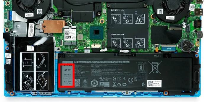
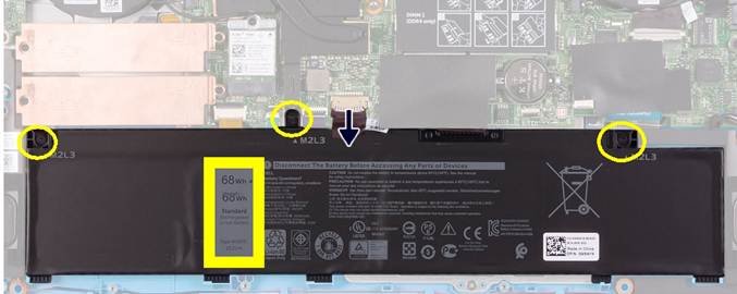
(which on dell g3 3500 laptop model has two type capacity of 51Wh(266J9) and 68WH(MV07R) .Please choose the battery as the same your original laptop battery model)
9. Disconnect the battery cable from the system board. NOTE: Disconnect the battery cable only when you are continuing to remove other components from your computer.
2>Removing the memory modules(DDR)
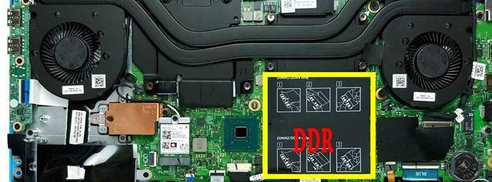
10.Lift the mylar to uncover the memory module.
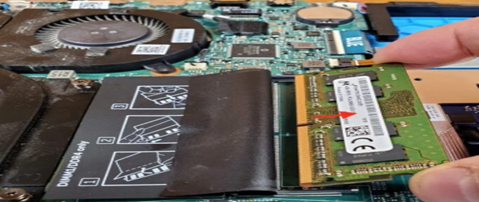
11.Use your fingertips to carefully spread apart the securing-clips on each end of the memory-module slot until the memory module pops-up.
12.Remove the memory module from the memory-module slot.
3>Removing the WLAN card
Steps
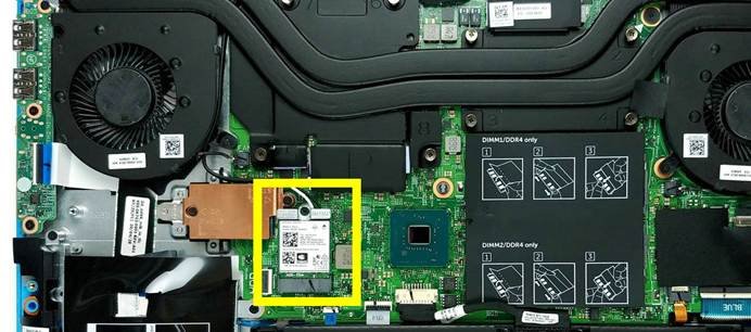
- Remove the screw (M2x3) that secures the WLAN card to the system board.
- Remove the bracket that secures the WLAN card to the system board.
- Disconnect the antenna cables from the WLAN card.
- Removing the 2280 solid-state drive
Steps
- Remove the two screws (M2x3) that secure the solid-state drive bracket to the system board and the palm-rest and keyboard assembly.
- Lift the solid-state drive bracket off the palm-rest and keyboard assembly.
- Slide and lift the solid-state drive/Intel Optane memory module off the SSD1 slot on the system board.
- Removing the left fan and right fan with heatsink
Steps
- Disconnect the left-fan cable from the system board.
- Remove the antenna cables from the routing guide on the left fan.
- Remove the two (M2x3) screws that secure the left fan to the palm-rest and keyboard assembly.
- Lift the left fan off the palm-rest and keyboard assembly.
6 Removing the speakers
Steps
- Disconnect the speaker cable from the system board.
- Note the routing of the speaker cable, and remove the speaker cable from the routing guides on the palm-rest and keyboard assembly.
NOTE Note the position of the rubber grommets before lifting the speakers.
- Lift the speakers, along with the cable, off the palm-rest and keyboard assembly.
7.Removing the power-adapter port
Steps
- Remove the screw (M2x4) that secures the power-adapter port bracket to the system board.
- Remove the power-adapter port bracket from the system board.
- Peel away the mylar that covers the power-adapter port cable connector on the system board.
- Peel away the tape that secures the power-adapter port cable on the system board.
- Disconnect the power-adapter port cable from the system board.
- Lift the power-adapter port, along with its cable, off the palm-rest and keyboard assembly.
8:Removing the system board
Steps
- Open the latch, and disconnect the display cable from the system board.
- Open the latch, and disconnect the keyboard-backlight cable (optional) from the system board.
- Open the latch, and disconnect the fingerprint-reader cable (optional) from the system board.
- Open the latch, and disconnect the touchpad cable from the system board.
- Open the latch, and disconnect the battery cable from the system board.
- Open the latch, and disconnect the keyboard-backlight cable (optional) from the system board.
- Open the latch, and disconnect the keyboard cable from the system board.
- Remove the two (M2x3) screws that secure the USB Type-C bracket to the system board.
- Lift the USB Type-C bracket off the system board.
NOTE When replacing the system board, the USB Type-C bracket has to be removed from the existing system board, and transferred to the replacement system board.
- Disconnect the speaker cable from the system board.
- Remove the two (M2x2) screws that secure the system board to the palm-rest and keyboard assembly.
- Turn the system board over, and disconnect the I/O board cable from the system board.
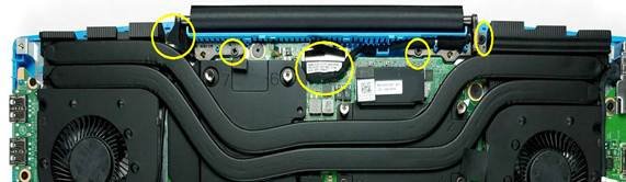
9: Unscrew the LCD Display Assembly
- Open the LCD screen and separate it from the palmrest.
- Unroute the WiFi antenna cables underneath the heatsink before completely separating the
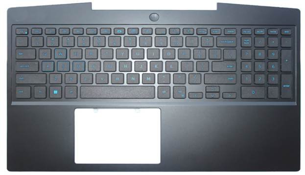
10:KEYBOARD WITH PLAMREST
Leave a Reply